Updated 20 June 2020
This document describes our investigations into the performance characteristics and limitations of automating manual resuscitator bag compression.
Waveforms for a set of ISO-based test settings are obtained via both a data-driven approach where response data is collected using an ASL 5000 breathing simulator connected to the ventilator, and via a model-based approach, where the breathing circuit, the lung and the flow profiles are modeled in MATLAB and Simulink. We also matched the model with hand calculations.
Flow/Motion Profile, Pressures & Volumes
In volume control ventilation, a common approach is to supply volume at a constant flow during the inspiratory time. This requires a short rise time and short fall time to approximate a square wave, shown at left in Figure 2, as closely as possible. The peak inspiratory pressure (PIP) for a constant flow profile is expected at the end of the inhale duration when maximum pressure due to compliance is added to the constant pressure due to the constant flow flowing through the airway resistance. Ideally, a perfect constant flow achieves a minimum peak flow needed to deliver a specified tidal volume.
For the Emergency Ventilator this requires a very high acceleration of the arms at the beginning of a breath. This leads to a consistent resistance pressure and growing compliance pressure. As an alternative, physicians recommend a decelerating flow profile, whereby the flow starts high and decreases to zero as the desired Tidal Volume is reached, shown at middle in Figure 2. A triangular flow covering the same area (delivered tidal volume) as a constant flow would require a peak flow that is twice that from a constant flow profile.
A Review of Waveform Patterns is provided in Respiratory Therapy magazine. Note that the flow rate (Q) is directly related to the mechanical velocity (vel).
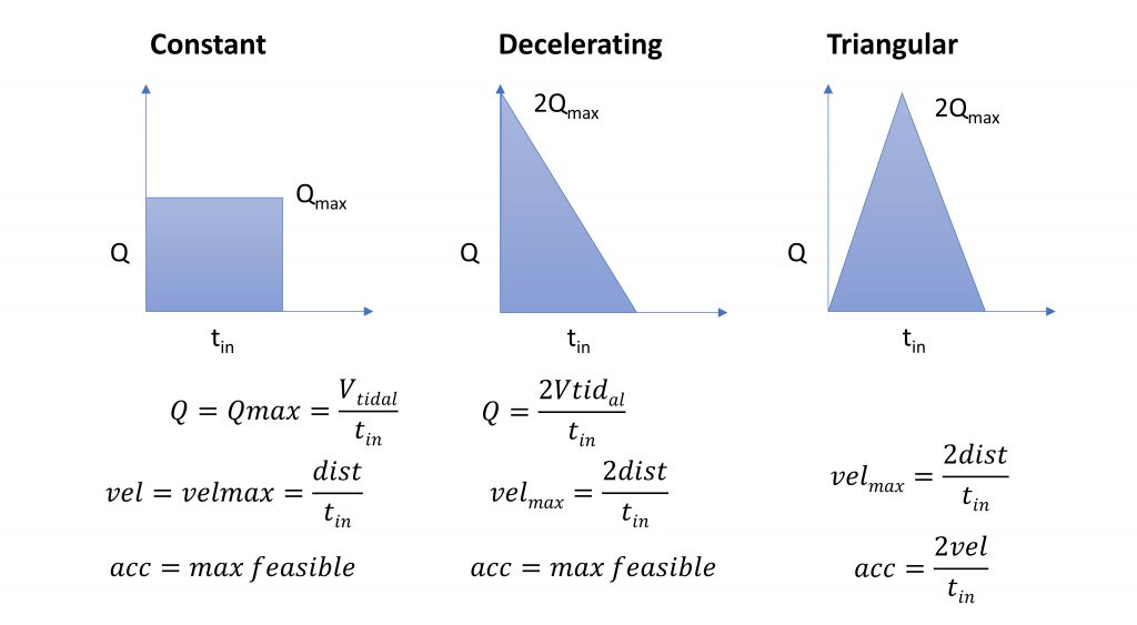
The triangular flow profile was developed in response to testing, which indicated that the Emergency Ventilator motor and controller were struggling to achieve the “infinite” acceleration necessary to ramp up to a constant flow profile. This is a compromise flow / motion profile, shown at right ion Figure 2, whereby the motor speed ramps up and then down. If the max velocity exceeds the motor capabilities, it can be capped for a trapezoidal flow.
ISO Based Testing
The testing of ventilator technology function is directed by ISO 80601-2-80, Medical Electrical Equipment – Part 2-80: Particular requirements for basic safety and essential performance of ventilatory support equipment for ventilatory insufficiency. We are using the First Edition 2018-02, obtained via the AAMI COVID-19 website which AAMI and ISO graciously made available.
The ISO standard specifies testing protocols for both Volume and Pressure Control modes, with a range of lung parameters (Compliance, Resistance) and ventilator settings (Volume, Frequency, PEEP). The inspiration time is set to 1 second, hence I:E ratios vary. The grid of tests is reproduced in Table 1, where the first 8 rows are directly from ISO 80601-2-79:2018.
Of particular interest is understanding:
- the shape of the pressure signal
- the flow signal and its peak values
- the delivered tidal volume signal
- the settings for which the pressure exceeds 40 cm H2O
Additional general requirements from ISO 80601-2-79:2018 specify that for volume-controlled breath types, during the testing, the error of:
- the delivered volume of individual breaths shall not deviate by more than 35 %.
- the delivered volume averaged over a one-minute interval shall not deviate by more than 25 %.
We use cm H2O for pressure instead of hPa in generating the data and for test settings where 1cm H2O is within 2% accuracy of 1 hPa (1cm H2O = 0.980665 hPa).
Both resistance and compliance create backpressure during operation, which can affect the actual volume delivered to the patient, as well as requires system power. Resistance includes resistance in both the patient’s lungs and the breathing circuit. Compliance is a function of both the patient’s lungs, flexibility in the breathing circuit components and compressibility of air. On some industry standard ventilators, resistance and compliance in the circuit can be compensated for within the ventilator settings.
| Test # | Compliance (ml/hPa*) ±10% | Linear Resistance (hPa*/L/s) ±10% | Volume (ml) | Ventilator Frequency1 (breaths/min) | Inspiratory Time (s) | PEEP (hPa*) |
| 1 | 50 | 5 | 500 | 20 | 1 | 5 |
| 2 | 50 | 20 | 500 | 12 | 1 | 10 |
| 3 | 20 | 5 | 500 | 20 | 1 | 5 |
| 4 | 20 | 20 | 500 | 20 | 1 | 10 |
| 5 | 20 | 20 | 300 | 20 | 1 | 5 |
| 6 | 20 | 50 | 300 | 12 | 1 | 10 |
| 7 | 10 | 50 | 300 | 20 | 1 | 10 |
| 8 | 10 | 20 | 200 | 20 | 1 | 5 |
| 9 | 10 | 20 | 200 | 25 | 1 | 5 |
| 10 | 10 | 20 | 200 | 30 | 1 | 5 |
Tests 6 – 8 specify flow resistances (50) that are not likely seen in an adult patient; typical resistances should not exceed 10 cmH2O/(L/s). Higher resistances are seen with pediatric patients, where endotracheal tubes can be as small as 3 mm in diameter. Two additional tests, 9 & 10, were suggested by our clinical team to simulate high respiratory rate and low Tidal Volume situations seen with ARDS & COVID patients.
We did not identify specific guidelines for errors in breath frequency, inspiratory time or PEEP. We note that PEEP is set manually, but can be set more accurately using the display of the Emergency Ventilator.
Note: The ISO standard specifies many more details regarding how ventilation parameters are set and displayed, alarms, electrical safety and labelling requirements. Please consult the standard – our information is not comprehensive.
Equipment
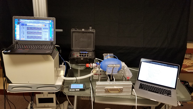
The ASL 5000 Breathing Simulator contains a screw-driven piston, encoder and pressure sensor. By measuring displacement, the encoder reports both volume and flow rate while a control loop replicates a wide range of patient profiles, both passive and active.
The ASL 5000 provides a number of key features:
- Adjustable patient compliance (mL/cmH2O) and resistance (cmH2O/(L/s))
- Measurement of volume delivered – this is measured directly
- Measurement of volume flow rate – this is obtained by differentiation
- Measurement of pressure and reporting of PEEP, PIP, Plateau
- Display and logging of volume and pressure waveforms over time
- Ability to take inspired breaths – we are using this to test Assist Control
- Ability to change profiles over time (we do not use this feature)
Our ASL 5000 was graciously loaned to us by Thomas Jefferson University with the direct support by IngMar Medical. Our test setup is shown in Figure 1.
Calibration
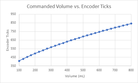
Prior to testing, the Emergency Ventilator was calibrated for an Ambu Oval Silicone Resuscitator. The resulting slightly quadratic curve is shown in Figure 3. This curve starts at 300 ticks, the rest position measured from zero, just touching the bag. The curve is given by:
ticks = -b + frac{sqrt{b^{2} - 4times atimes (c - volume)}} {2a}
a = 1.29times 10^{-3}; b = 4.73times 10^{-1}; c = -7.35times 10^{1}
This calibration is specific to each bag and system and by inspection is approximately linear. This curve was used to set the mechanical endpoints as a function of desired Tidal Volume, but not to adjust the motion profile.
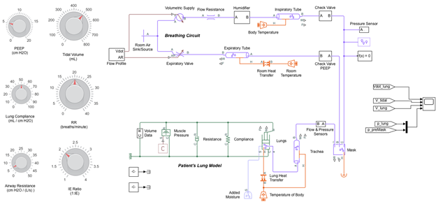
Simulink Model Based Waveforms
The Emergency Ventilator was modeled in Simulink for both the constant flow and triangular flow profiles as shown in Figure 4. The results for both flow profiles are compared in Figure 5. The model, shown in Figure 4, combines a breathing circuit with a patient lung model and has settings for Tidal Volume, Respiratory Rate and I:E. The patient and breathing circuit compliance and resistance as well as PEEP can be adjusted and the flow profile can be changed from constant to triangular.
Click here to download the Simulink model.
More data is available in the full report. Figures 5 and 6 show the model responses for ISO Test #4 for a Constant Flow and Triangular Flow profile and Figure 7 shows the results when the Emergency Ventilator is connected to the ASL breathing simulator. The specific parameters of this test represent an unhealthy patient with low compliance (20 ml/cmH2O) a very high resistance (20 cmH2O*/L/s) and a high peep setting (10 cmH2O). The Tidal Volume (500 mL) and respiratory rate (20 BPM) are typical. In this case both a high resistance and compliance pressure are expected.
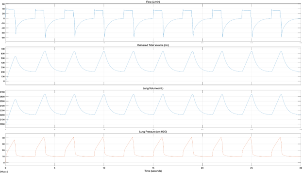
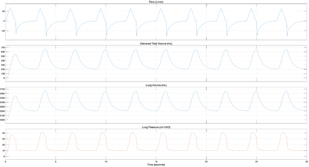
From these models, we can clearly see two distinct motion profiles in the flow plots, that the tidal volume delivered is about 40 mL less than the commanded, the retained volume in the lungs and circuit and that with both profiles, the PIP exceeds 40 cmH2O. This overpressure will both trigger and alarm on the Emergency Ventilator and cause the pop-off valve to vent.
According to these model-based simulations, Tests #4 and #7 exceed 40 cm H2O when a constant flow is used, while Tests #4, #6, and #7 exceed 40 cm H2O when a triangular flow profile is used.
Calculated Values
Based on the model results for volume delivered (Delivered VT) a number of values can be calculated for the constant flow case. These help in better understanding the model and actual responses observed.
PIP[1] = Flow*Resistance + Delivered VT/Compliance
(this is the first breath)
PIP[2] = PEEP + Flow*Resistance + Delivered VT/Compliance
(subsequent breaths)
The first breath delivers the initial bolus of air which will be incompletely expelled, as a function of PEEP. Therefore, the retained volume and compliance together contribute to baseline pressure going forward.
The Emergency Ventilator operates by moving the arms to deliver a desired tidal volume (VT) determined by the calibration and specified to the controller as a set position, in encoder ticks. However, this air cannot pass into the patient valve until it is compressed and pressurized. Therefore, the delivered volume is reduced due to a compression volume and tubal compliance losses. Using Mechanical Ventilation by Shelledy and Peters, we estimate this to be a function of the driving pressure (PIP – PEEP) and a compressibility factor of 1.154:
Delivered VT = VT – (PIP – PEEP) * compressible volume ratio
Note: This factor was not applied to cases #1 and #2 where the volume delivered was observed to be almost the commanded volume.
Important: Given the flexible nature of the manual resuscitator bag and the fact that its entire volume must be compressed, though not expelled, we expect the Emergency Ventilator to have a greater compression volume losses than typical ventilators.
Note: In the test setup, shown in Figure 1, only the air in the bag must be compressed, but in the correct breathing circuit, shown in Plumbing, there is a second one-way patient valve and, therefore, the air in the extension tube must also be compressed.
Finally, the volume remaining in the lung after exhale can be calculated:
End-expiratory lung volume = FRC + PEEP*Compliance. These calculations are performed for ISO Test #4:
PIP1 = Flow*Resistance + Delivered VT/Compliance
38.11 cm H2O = (0.5/0.90)*20 + 540/20 = 11.11 + 27
PIP2 = PEEP + Flow*Resistance + Delivered VT/Compliance
44.11 cm H2O = 10 + (0.5/0.90)*20 + (660-200)/20 = 10 + 11.11 + 23
Delivered VT = VT – (PIP – PEEP) * compressible volume ratio
460.64 mL = 500 – (44.11-10)*1.154
End-expiratory lung volume = FRC + PEEP*Compliance
2200 mL = 2000 mL + 200 mL
ASL Waveform Testing Results
In parallel with the modeling effort we recorded data with the ASL 5000, reading values from both the ASL’s automated calculations and the displayed waveforms directly. During the runs, we deliberately disabled the pop off valve in order to record maximum pressures. The data from ISO Test #4 is shown in Figure 7, which can be seen to agree in shape and values with the previously modelled triangular flow, Figure 6.
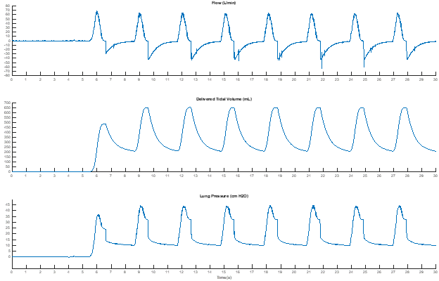
In general, as expected, the peak flow is consistent with the model-based simulations and is twice what a constant flow requires. Despite that, the PIP-Plateau pressure remains close to that in the constant flow profile, because the maximum pressure due to compliance and resistance do not line up in a triangular flow, unlike the case in the constant flow.
Based on the collected data, Tests #4, #6, and #7 exceed 40 cm H2O with the pop-off valve disabled. This is consistent with the model-based observations from where the triangular flow profile also resulted in a pressure build up exceeding 40 cm H2O for Tests #4, #6, and #7.

Cool, FYI: FDA will request that type of information if you go through EUA.
Hello! Congratulations on the project!
What is the total weight of the project?
hey, can anyone tell me? if I can do any flow analysis on Ambu Bag or any other Ansys simulation. if yes, then please share the information regarding this.
Hello,
Congrats for this challenging project!
In this page, for conversion of volume to ticks, the at the Calibration section for Ambu Oval Silicone Resuscitator it is indicated a formula which is a bit different than the one used in the code from GitHub.
In this page the formula is like this:
ticks=−COEFFS.b + (sqrt(sqr(COEFFS.b) – 4 * COEFFS.a * (COEFFS.c – vol_ml))) / (2 * COEFFS.a);
In the code from GitHub the formula is:
“float volume2ticks(const float& vol_ml) {
return (-COEFFS.b + sqrt(sqr(COEFFS.b) – 4 * COEFFS.a * (COEFFS.c – vol_ml))) / (2 * COEFFS.a);
}”
The difference is from position of the -COEFFS.b inside or outside of the “()”
Am I missing something?
Dear sir
great what you are achieve here man
I am working in the same project but I change the motor and used Stepper motor.
now I want to know how to calculate the following parameters :
TV, RR , I/E , TRIG (AC)
please help me here